Difference between revisions of "Tutorials:Cadence:CreatingBehavioralModel"
| Line 35: | Line 35: | ||
: [[File:Tutorials-Cadence-Verilog2.gif]] | : [[File:Tutorials-Cadence-Verilog2.gif]] | ||
| + | |||
| + | |||
| + | [[Tutorials:Cadence:VerilogHDL|Prev]] : [[Tutorials:Cadence:VerilogSimulation|Next]] : [[Tutorials:Cadence:Main|Up]] | ||
---- | ---- | ||
{{Template:CadenceDisclaimer}} | {{Template:CadenceDisclaimer}} | ||
Revision as of 17:14, 10 November 2010
Creating a Verilog Model for an Inverter
We'll now create a Verilog description of the inverter.
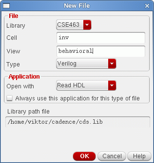
In your library manager click once on the CSE463 library and then click once on the inv cell view. Now left click Library manager: File → New → Cell view. In the dialog box type behavioral in the View field. Select Verilog for the Type. The New File window should look like the one below:
Left click OK. The text tool should now appear, with some basic template stuff inside. Anything preceded by a "//" is considered to be a comment.
An Emacs editor window will pop up. Add the following the statement in between the module statements:
not (out, in);
If the input and output names are not "in" and "out" for you, substitute them with your own names. The (out, in) syntax specifies the output and input for the inverter. In Verilog, the convention is that the output arguments of the module (gate) are listed before going on to the inputs.
This is all the text you need in order to describe your inverter. Now you can save the text file and close it. Cadence will tell you in the CIW whether the functional view is successfully parsed (no syntax errors) or not.
Now you are ready to simulate your Verilog code.
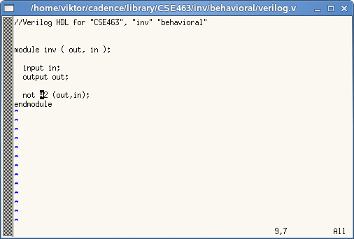
The commands that you used in the text file are described below:
- module
- Defines the beginning of a Verilog module.
- inv(...)
- Specifies the name of the module. All pins (connections to the outside world) must be specified inside the parenthesis.
- in/out
- Defines what the input/output pins into the module are.
- not
- Tells that this gate is an inverter. There are three basic gates: AND, OR, NOT, NAND, and NOR.
- endmodule
- Signifies the end of this particular module.
The final model file should look like the one below:
Information is provided "as is" without warranty or guarantee of any kind. No statement is made and no attempt has been made to examine the information, either with respect to operability, origin, authorship, or otherwise.
Please use this information at your own risk--and any attempt to use this information is at your own risk--we recommend using it on a copy of your data to be sure you understand what it does and under what conditions. Keep your master intact until you are personally satisfied with the use of this information within your environment."
Cadence® is a trademark of Cadence Design Systems, Inc., 555 River Oaks Parkway, San Jose, CA 95134
For web related questions contact: Viktor Gruev, Michael Hall

